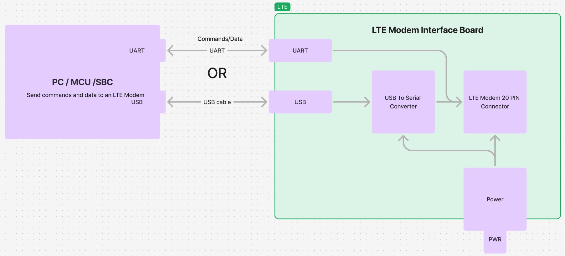

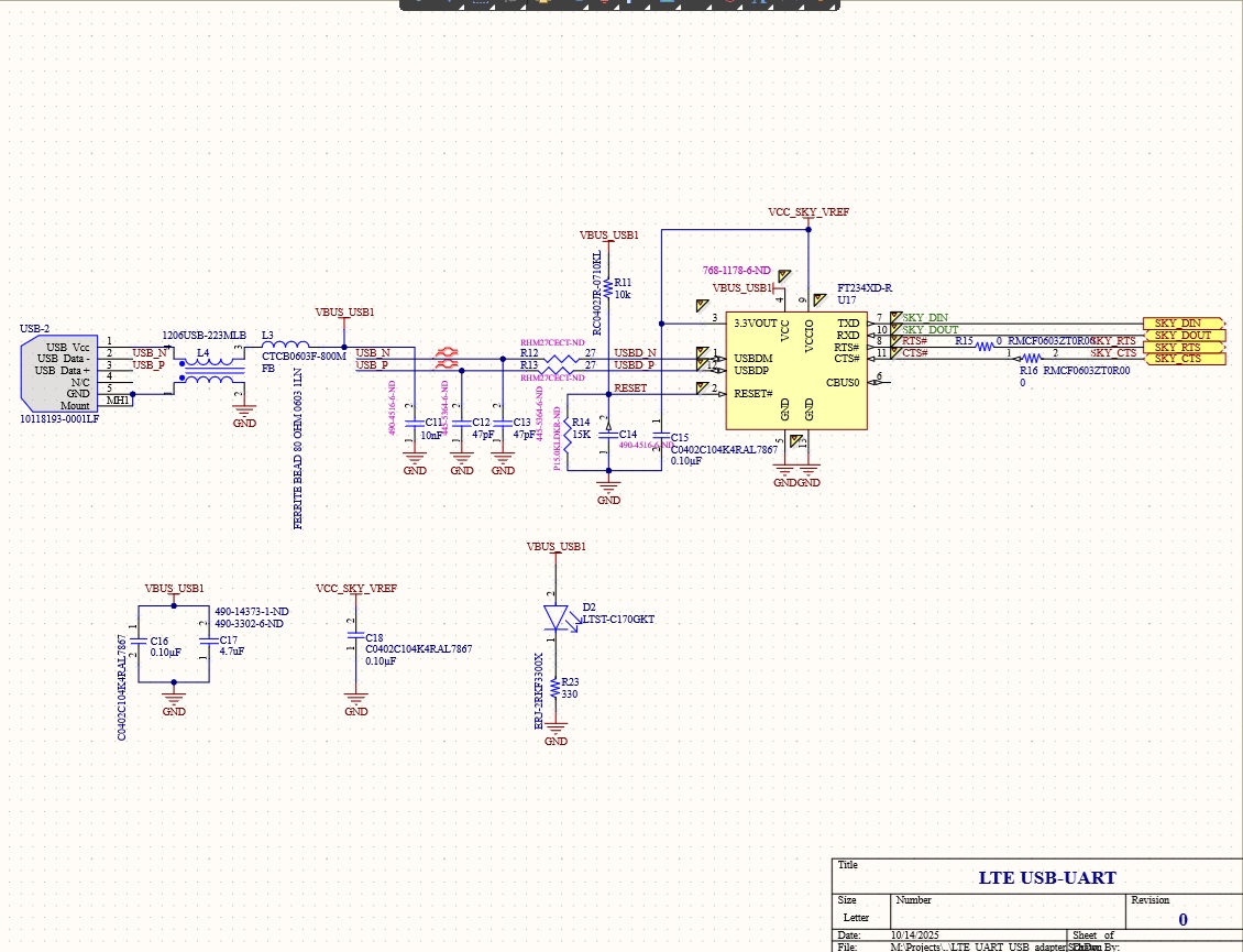
The LTE modem interface board is designed to relay LTE commands and data over USB or UART connection
When an LTE cell modem is connected to a computer via USB or to a microcontroller/microprocessor through a UART communication port,
it establishes a communication channel for transferring data between the modem and an electronic device. This data may include LTE
commands sent from the device to the modem, such as requests for network information or specific actions, as well as LTE payloads,
which consist of the actual data packets transmitted or received over the cellular network. The USB connection offers a reliable and
efficient method for the computer to interact with the LTE device and manage its cellular connectivity.
The LTE modem interface board is designed to seamlessly integrate LTE capabilities into existing microprocessor designs.
It incorporates the necessary hardware components to enable the microprocessor to connect to a cellular
network and transmit or receive data using LTE technology. By leveraging existing microprocessor infrastructure,
our solution offers a cost-effective and efficient way to add LTE connectivity to various applications. The board
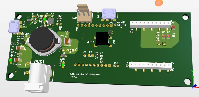
dimensions are 3.8 x 1.535 inches.
The board is designed to work with
Airgain (NimbeLink) cellular embedded modems.
We can customize this design to suit any existing product.
NimbeLink Cellular Embedded Modems are engineered to deliver
reliable, efficient cellular connectivity for a wide range of IoT applications. These modems are compact and easy to integrate
into various devices, making them ideal for products requiring remote monitoring, control, or data transmission.
We recommend the
2JP0524P Antenna
for the LTE modem, although any other high-performance 4G LTE/3G/2G antenna will also work.
Key benefits of using NimbeLink modems include:
Board customization offers flexibility in adapting the design to specific product requirements. This can involve:
By customizing the board design, you can create a solution that is tailored to your exact requirements, ensuring optimal performance and functionality. This can help you differentiate your product in the market and achieve your business goals.
The Interface board as delivered.
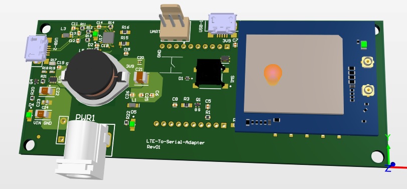
The Interface board with LTE module installed. An LTE module can be purchased at Airgain.
Install the LTE module as shown in the picture below. Line up your Skywire's cellular U.FL connector(s) toward the edge of the board, as shown in the image below. Depending on the type of Skywire Modem you have
there may be one, two, or three U.FL connections. To avoid damage to the U.FL connector and maximize connector life, a U.FL
removal tool should be used when attaching/removing the U.FL connector. Always insert and remove the U.FL connector with a force perpendicular to the
board. If your Skywire is using GPS, attach the GPS antenna to the bottom of the Skywire connector X3.
Attach the U.FL cable to the top U.FL connector X1 on the Skywire. If you are using a Skywire with the cellular diversity antenna option attach a second
antenna to connector X2.
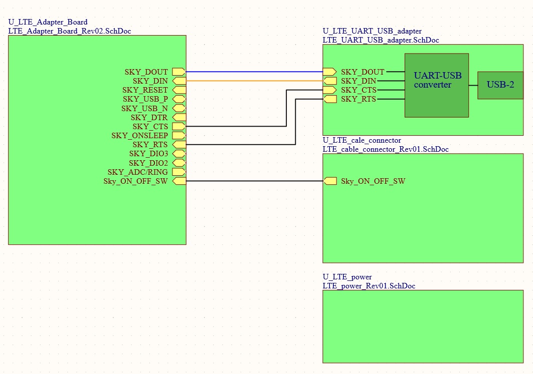
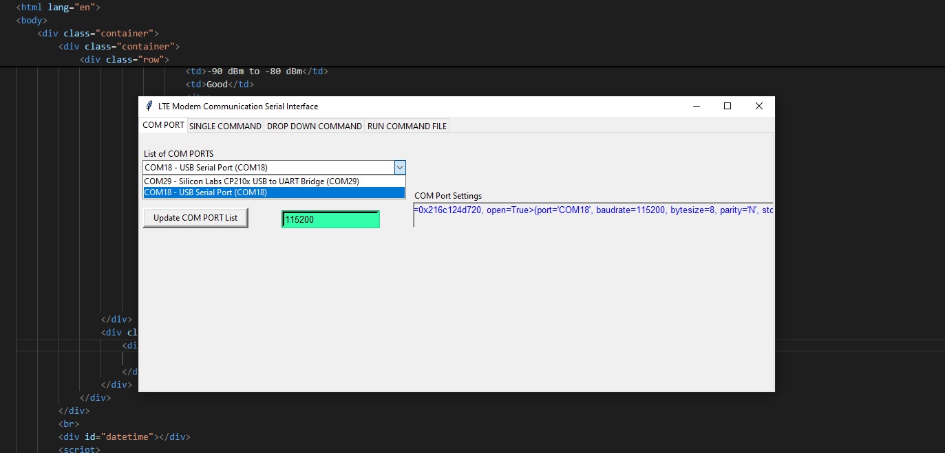
The board is featuring a USB and UART communication lines.
Connect your device to the modem UART or USB-2 port and send AT commands directly to the modem through PC terminal applications.
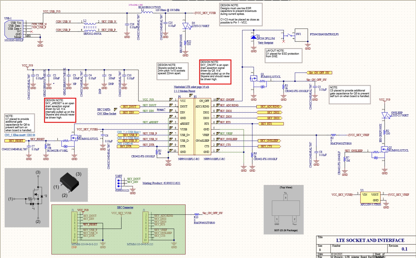
To connect the board to a processor or development kit, a 20-pin header breaks out the necessary signals for easy connection to any device.
The LTE modem/board supports I/O levels from 1.65-5.5V.
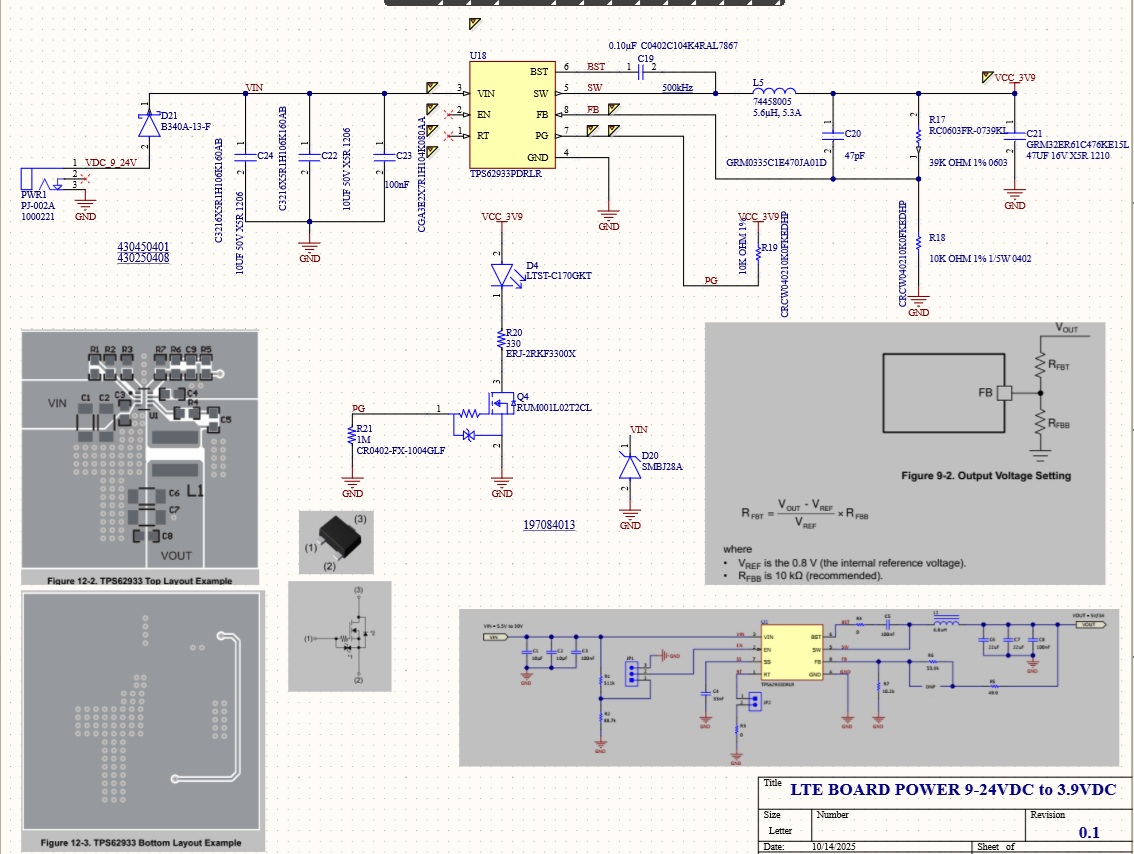
Plug in 12V Power Supply to connector PWR1.
Plug USB cable into connector USB-2 and PC.
Power On the Modem: Press and hold button SW1 to power on the modem. Please see the table below for the length of time needed to hold down button SW1 for your particular modem.
| Device Power ON Table | |||
|---|---|---|---|
| Device | Hold Time (th) | Wait Time (tw) | ON/SLEEP LED Activity |
| NL-SW-1xRTT-A | 1 second < th < 2 seconds | tw > 10 seconds | Blink once |
| NL-SW-1xRTT-S | 1 second < th < 2 seconds | tw > 10 seconds | Blink once |
| NL-SW-1xRTT-V | 1 second < th < 2 seconds | tw > 10 seconds | Blink once |
| NL-SW-GPRS | th > 5 seconds | tw > 10 seconds | Blink once |
| NL-SW-EVDO-A | 1 second < th < 2 seconds | tw > 10 seconds | Blink twice |
| NL-SW-EVDO-V | 1 second < th < 2 seconds | tw > 10 seconds | Blink twice |
| NL-SW-HSPA | th > 5 seconds | tw > 2 seconds | Solid on |
| NL-SW-HSPA-B | th > 5 seconds | tw > 2 seconds | Solid on |
| NL-SW-LTE-TSVG | 1 second < th < 2 seconds | tw > 15 seconds | No activity |
| NL-SW-LTE-TNAG | 1 second < th < 2 seconds | tw > 15 seconds | No activity |
| NL-SW-LTE-TEUG | 1 second < th < 2 seconds | tw > 15 seconds | No activity |
| NL-SW-LTE-GELS3 | 1 second < th < 2 seconds | tw > 30 seconds | Solid on |
| NL-SW-LTE-WM14 | n/a (Done in Section 2.5) | tw > 30 seconds | Solid on |
| NL-SW-LTE-QBG96 | th > 1 second | tw > 4 seconds | Solid on |
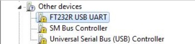
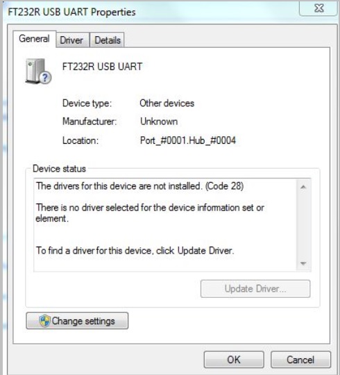
Install FTDI driver (Windows):
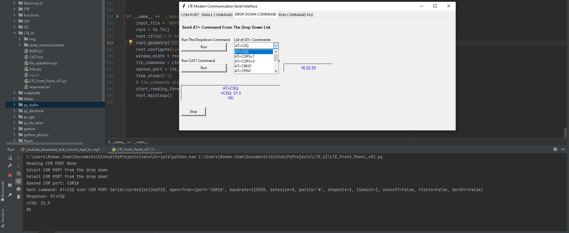
We're currently developing an open-source Python user interface to communicate with an LTE modem via the USB-2 connector.
The code will be accessible on GitHub.
Test Serial Communication:
In the terminal program, type the command: AT followed by the Enter key, and the terminal should respond with: OK
Note: For the NL-SW-LTE-WM14, you will not see the characters you have typed until hitting the enter key.
You may need to turn echo on in order to see what you are typing. If you type the command: AT and don't see it being typed on
your screen, hit the Enter key, and type the following command: ATE1 followed by the Enter key, and the terminal program should
respond with: OK
Type the following command: AT to verify you can see the command you are typing. After pressing the Enter key, the terminal
program will respond with: OK.
Note: The modem will output "ERROR" when a command is entered incorrectly. To enable verbose error mode to see what error is occuring issue
AT+CMEE=2 to the modem.
Test Signal Strength:
For Non-LTE Modems - In the terminal program, type the command: AT+CSQ followed by the Enter key, and the terminal should
respond with: +CSQ: xx,yy
where xx is the signal strength of the antenna, and yy is the bit error rate in percent. Typical values are as follows:
| Device Signal Quality | |||
|---|---|---|---|
| Values of xx Relative Signal Strength | Signal Quality | dBm Range | |
| 0 - 9 | Poor | ≤ -95 dBm | |
| 10 - 14 | OK | -93 dBm to -85 dBm | |
| 15 - 19 | Good | -83 dBm to -75 dBm | |
| 20 - 30 | Excellent | -73 dBm to -53 dBm | |
| 31 | Excellent | ≥ -51 dBm | |
| 99 | Not known or not detectable | N/A | |
| Device Bit Error | |||
|---|---|---|---|
| Values of yy Bit Error Rate | Bit Error Rate Range | ||
| 0 | Less than 0.2% | ||
| 1 | 0.2% - 0.4% | ||
| 2 | 0.4% - 0.8% | ||
| 3 | 0.8% - 1.6% | ||
| 4 | 1.6% - 3.2% | ||
| 5 | 3.2% - 6.4% | ||
| 6 | 6.4% - 12.8% | ||
| 7 | More than 12.8% | ||
| 99 | Not known or not detectable | ||
For LTE Modems
To check the signal strength on an LTE modem the user should refer to the RSRP (Reference Signal Received Power) & RSRQ
(Reference Signal Received Quality) values reported by the modem. These signal measurements will more accurately reflect
the quality of the cellular link for LTE modems by not only measuring rsrq is the Reference Signal Received Quality
(RSRQ) and rsrp is the Reference Signal Received Power (RSRP). Typical values are as follows:
| Values of |
Reference Signal Received Quality Range |
|---|---|
| 0 | ≤ -19.5 dB |
| 1 | -19.5 dB to -19 dB |
| 2 | -19 dB to -18.5 dB |
| ... | ... |
| 32 | -4 dB to -3.5 dB |
| 33 | -3.5 dB to -3 dB |
| 34 | ≥ -3 dB |
| 255 | Not known or detectable |
| Values of |
Reference Signal Received Power Range |
|---|---|
| 0 | ≤ -140 dBm |
| 1-94 | -140 dBm to -45 dBm (incrementing by 1 dBm) |
| 95 | -46 dBm to -45 dBm |
| 96 | -45 dBm to -44 dBm |
| 97 | ≥ -44 dBm |
| 255 | Not known or not detectable |
Here are estimated signal qualities based on the above values:
| RSRQ Values | RSRQ Range | RSRP Values | RSRP Range | Quality |
|---|---|---|---|---|
| 0 | ≤ -19.5 dB | 0-40 | ≤ -100 dBm | Marginal |
| 1-9 | -19.5 dB to -15 dB | 41-50 | -100 dBm to -90 dBm | Fair |
| 10-19 | -15 dB to -10 dB | 51-59 | -90 dBm to -80 dBm | Good |
| 20-34 | ≥ -10 dB | 60-97 | ≥ -80 dBm | Excellent |
| 255 | Not known or detectable | 255 | Not known or detectable | Unknown |